Low Energy Positron Trap
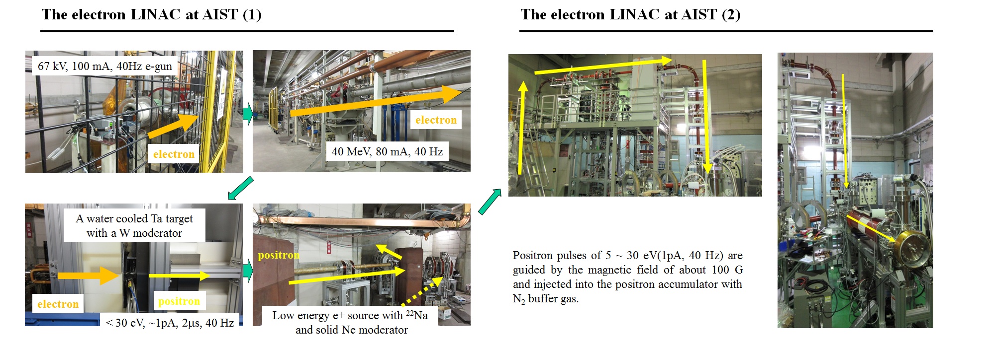
The electron LINAC at National Institute for Advanced Industrial Science and Technology (AIST)
For the use of positrons in a laboratory, one of the following techniques can be used nowadays.
1) radio isotopes which emit positrons
2) an electron linear accelerator (LINAC) which injects high energy electron beams into a target and create positrons through pair creation
3) neutron beams from a nuclear power plant.
In any case, created positrons have high energies with a large energy spread. In general, a moderator is used to obtain useful low energy positron beams.
The electron LINAC at AIST inject ~ 40 MeV electron pulses into a water cooled Ta target and the created high energy positrons are slowed down with a W moderator.
Controlling the bias potential of the W moderator, 5 ~ 30 eV positron beams are available for various experiments.
A LINAC based low energy positron accumulation
To study electron-positron plasmas experimentally, 10^8 positrons are required at least. Here, with the use of the LINAC at AIST, a LINAC bassed low energy positron accumulation technique is developed, which has been pursued since 1990's. GBAR collaboration at CERN AD also uses a LINAC to accumulate positrons to produce antihydrogen atoms.
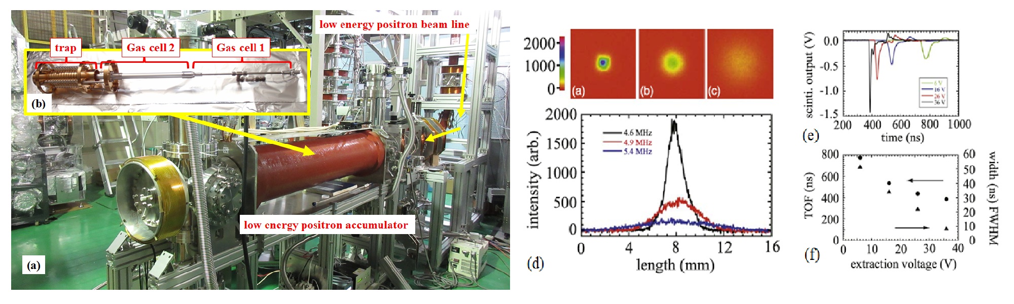
The picture (a) below shows the low energy positron accumulator installed at the end of the low energy positron beam line. The gas cells and trap electrodes shown in the inset (picture (b)) inside the vacuum chamber are housed in the water cooled solenoid coil which can produce 900 G at the maximum.
Figures on the right below show some examples of positron accumulation tests. Figures (a)-(c) show the images of the extracted positron pulses measured with a multi-channel plate and a phosphor screen. After 4 sec accumulation inside the trap with a rotating wall technique, it is seen that the density of the confined positrons can be controlled with a specific RF frequency. Figure (d) shows the cross sections of (a) - (c). Also, shown in Fig.(e) are the annihilation signals of the extracted positron pulses with a different extraction voltages. The measured time of flight (TOF) and pulse width of the annihilation signals are plotted in Fig.(f).
References
H.Higaki, C. Kaga, K. Nagayasu, H. Okamoto, Y. Nagata, Y. Kanai and Y. Yamazaki, AIP Conf. Proc. 1668 (2015) 040005
H.Higaki, K. Michishio, K. Hashidate, A. Ishida and N. Oshima, Appl.Phys.Express 13 (2020) 066003
S. Niang, M. Charlton, J. J. Choi, et.al., Acta.Phys.Pol. A 137 (2020) 164
Back to the top