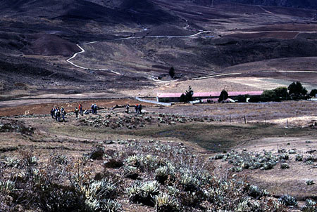
Photo 7. The trench site viewed from north. The trench was excavated across the sag and shutter ridge, on which the participants are making hot discussion on where to dig.
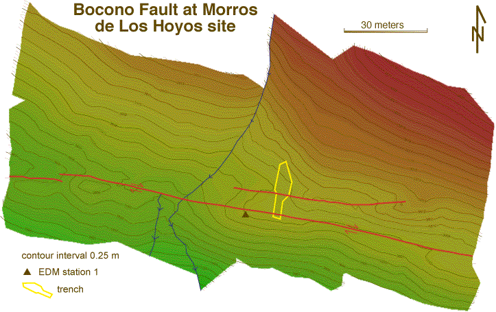
Figure 2. Detailed topographic map of the trench site prepared through EDM survey.
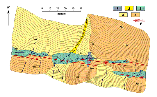
Figure 3. Preliminary geologic map of the trench site
Trench crossed two active traces of the fault, which has a pronounced right-stepping en echelon pattern associated with dextral strike-slip motion. Shutter ridges and peat-laden sag ponds are common along this reach of the fault. Patterns: 1, trench; 2 active alluvial channel deposits; 3, sag ponds (peats); 4, fan and older channel alluvium; 5, bedrock; 6, fault showing slip direction. Contour interval is 0.5 m. Triangle shows EDM base station for surveying (arbitrary elevation of 100.00 m).
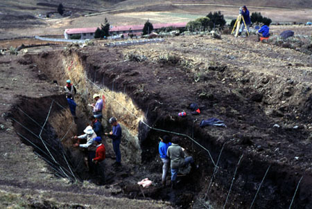
Photo 8. Clear high-angle fault was exposed in the middle of the trench. The soft dark sediments in the sag were too soft to be stable with vertical wall of American-style trench. Japanese technology of inclined wall trenching did good job for the east wall, that made logging a little complicated.
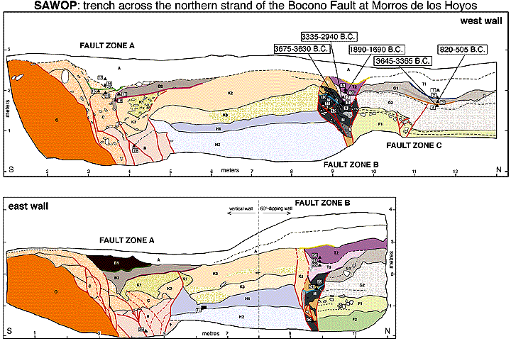
Figure 4. Logs of the trench wall
A. rooted loose brown soil, black at the base to the north especially in correspondence of the sag pond;
UNITS SOUTH OF FAULT ZONE
B: B1: organic sand and clay, locally soil infiltrated;
B2. organic silty clay, oxidized at the contact with A;
C: scarp derived colluvium, angular centimetric fragments mailny from O in a sandy to silty matrix, intensely sheared in the fault zone;
K1. poorly sorted angular gravel in sandy ocraceus matrix, alluvial channel?
K2. oxidized silty clay with local lenses of gravel;
K3. matrix rich, angular gravel, oxidized;
H1. gray clay with sparse bedrock fragments;
H2. gray pebbly sandy gravel; N. plastic grey-green clay with sparse bedrock fragments (same as H1-H2?), organics infiltrated along the fault planes;
O. metamorphic bedrock;
UNITS NORTH OF FAULT ZONE
B: T1 and T2. clay rich dark brown peat;
T3. pebbly peat mottled with brown clay in the fault zone;
M. dark brown peat mixed with fragments from bedrock,
K1-K2, and H1-H2; G1. coarse gravel in organic sandy matrix;
G2. poorly sorted brown gravel in granular sandy matrix;
F1. green angular poorly sorted gravel with a 5-10 cm-thick slity layer on top;
F2. green silty clay. Black triangles locate the samples collected for radiocarbon dating, rectangle locates sampling for thermoluminescence.
Colored dotted lines locates possible event horizons.
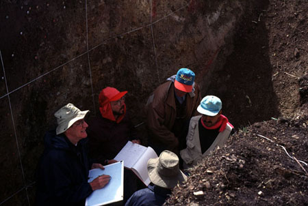
Photo 9. Dicussion for logging
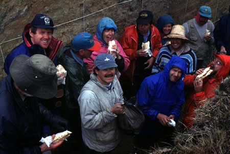
Photo 10. This is one the most crowded trenches that have ever worked out.