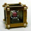
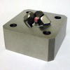
Multianvil Apparatus, etc.
I. Multianvil Apparatus (Cubic anvil, Kawai-type apparatas)
A multianvil apparatus allows us to perform:
・High-pressure experiments (at high temperature)
・High-pressure deformation experiments (at high temperature)
・In situ diffraction, radiography, spectroscopy and microscopy
(with synchrotron X-ray, neutron beam and light)
(phase identification, stress-strain measurements, etc.)
The high-pressure experiments with a multianvil apparatus enable us to study:
・Phase transitions, phase equilibria
・Physical properties
and are useful for:
・Studies on the Earth's interior and
・High-pressure synthesis of materials
The multianvil apparatus is classified by anvil system as:
・Kawai-type apparatus (multianvil 6-8 system)
・Cubic anvil apparatus (multianvil 6 or multianvil 6-6 system)
・Tetrahedral-type apparatus, etc.
The multianvil apparatus is also classified by compression system as:
・Uniaxial press (1 hydraulic ram with guide blocks)
・Tetrahedral press (4 hydraulic rams)
・Six hydraulic ram press (6 hydraulic rams)
・Deformation-DIA apparatus
Deformation T-Cup apparatus
(1 main and 2 differential hydraulic rams)
・Oil chamber (no hydraulic rams)
Some examples of the multianvil apparatuses will be introduced below.
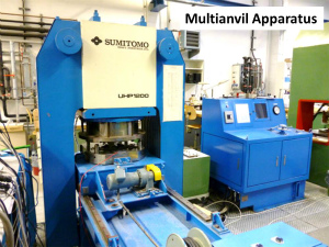
Fig. (1st) A Kawai-type multianvil apparatus made in 1989 (split-sphere
type, at Bayerisches Geoinstitut, University of Bayreuth).
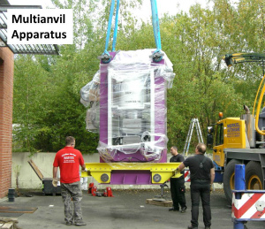
(2nd) Delivery of a Kawai-type multianvil apparatus (DIA-type, press load
capacity = 15 MN) to Bayerisches Geoinstitut in 2014.
(3rd) Pressure-temperature conditions of experiments with the multianvil
apparatuses in our experience (Kawazoe and Ohtani, 2006; Kawazoe et al., 2010 HPR; Kawazoe et al., 2010 PEPI; Ishii et al., 2016). |
 |
| 1. Kawai-type Multianvil Apparatus |
 |
A Kawai-type multianvil apparatus allows us to perform:
・High-pressure experiments (at high temperature)
・In situ diffraction, radiography and spectroscopy
(with synchrotron X-ray)
In the Kawai-type multianvil apparatus (multianvil 6-8 system; Kawai and Endo, 1970), sample pressure is generated by successive compression:
(1) Hydraulic ram(s) drive six first-stage anvils (via guide blocks).
(2) The six first-stage anivls compress eight second-stage anvils.
(3) The second-stage anvils compress an octahedral cell assembly.
The Kawai-type multianvil apparatus is classified by style of the first-stage anvils as:
・Split-cylinder type
・Split-sphere type
・DIA-type (Ohtani et al., 1989)
・Walker-type (one of split-cylinder type; Walker et al., 1990)
・Six hydraulic ram type
・Oil reservoir type (Kawai and Endo, 1970).
The maximum pressure conditions of the Kawai-type apparatus are primarily limited by hardness
(material, brand) of second-stage anvils:
・27 GPa (nominally-hard tungsten carbide)
(to 3040 K at 27 GPa; Kawazoe and Ohtani, 2006)
・44 GPa (the hardest tungsten carbide)
(to 2000 K, Ishii et al., 2016)
・109 GPa at room temperature, 106 GPa at 1200 K (sintered diamond)
(Yamazaki et al., 2014)
The second-stage anvils of the Kawai-type apparatus are characterized
by a truncated edge length, an edge length and material. As far as I know,
the truncated edge lengths are:
・0.5 mm (Ohtani et al., 1989)
・1.0 mm (Ohtani et al., 1989)
・1.5, 2.0, 3, 3.5, 4, 5, 8, 11 and 17 mm,
the edge lengths are:
・14, 26, 32 mm
・54 mm (Frost et al., 2004)
and materials are:
・Tungsten carbide
・Sintered diamond (e.g. Ohtani et al., 1989)
・Cubic boron nitride (synchrotron X-ray transparen).
The maxium pressure is generated with the second-stage anvils with smaller
truncated edge lengths of 1.5-2 mm.
Gasket is attached near a cell assembly and between the second-stage anvils to
generate sample pressure efficiently. The gasket also supports the second-stage
anvils by lateral support. Pyrophyllite is used as the gasket material in general (King, 1965).
Some examples of the cell assemblies for the Kawai-type apparatus are shown below.
Fig.
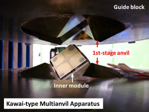
(1st) An inner module of the Kawai-type multianvil apparatus loaded on
lower first-stage anvils (just before compression). Upper first-stage anvils
are going to reach the second-stage anvils for compression.
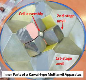
(2nd) The cell assembly, the second-stage anvils and the first-stage anvils
of a Kawai-type multianvil apparatus (split-cylinder type, press load capacity
= 50 MN, Frost et al., 2004).
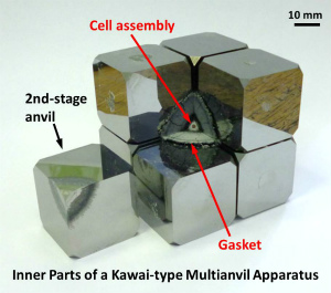
(3rd) The 10/5 cell assembly and the 32-mm second-stage anvils of a Kawai-type
multianvil apparatus after a high-pressure experiment.
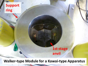
(4th) A Walker-type module for the Kawai-type multianvil apparatus (Walker et al., 1990).
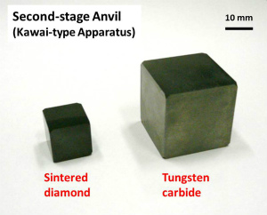
(5th) The second-stage anvils for the Kawai-type multianvil apparatus.
A sintered diamond anvil with a 14-mm edge length and a tungsten carbide
anvil with a 26-mm edge length. |
| 2. Deformation-DIA-type Multianvil Apparatus (D-DIA) |
 |
A deformation-DIA apparatus allows us to perform
・High-pressure deformation experiments (at high temperature)
・High-pressure experiments (at high temperature)
(as a cubic anvil multianvil apparatus)
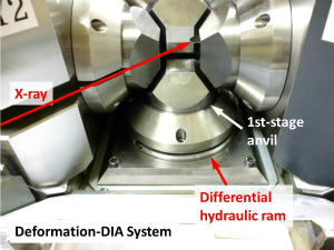
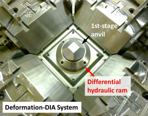
In the deformation-DIA system, two differential hydraulic rams are embeded behind top and bottom first-stage anvils in the upper and
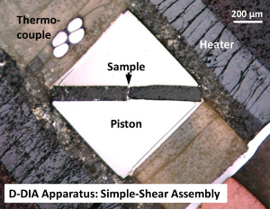
lower guide blocks (Wang et al., 2003). This deformation-DIA system allows deformation experiments in uniaxial geometry under high pressure. Deformation experiments in simple shear geometry are also possible adding shear deformation function to the cell assembly
(Ohuchi et al., 2010; Kawazoe et al., 2013).
The maximum pressure conditions of the deformation experiments with the deformation-DIA apparatus
are:
・20 GPa at 1700 K (with no in situ stress-strain measurements)
(Kawazoe et al., 2010 JES)
・15 GPa at 1700 K (with in situ stress-strain measurements)
(Kawazoe et al., 2011)
Our group combines the deformation-DIA apparatus with a multianvil 6-6 system, which will be introduced below.
Some examples of the cell assemblies for the cubic anvil apparatus are shown below.
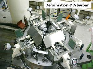
Fig. (1st) A lower guide block and four sliding (side ) blocks of the deformation-DIA
apparatus (at Geodynamics Research Center, Ehime University).
(2nd) The central part of the deformation-DIA guide block system (at BL04B1
beamline, SPring-8).
(3rd) The lower guide block of the deformation-DIA apparatus. The differential
hydraulic ram is embeded below a bottom first-stage anvil in the lower
guide block (at BL04B1 beamline, SPring-8). |
| 3. Multianvil 6-6 System (MA6-6) for a Cubic Anivl Apparatus |
 |
We have developed innovative multianvil techniques for a cubic anvil apparatus (e.g. Kawazoe et al., 2010 PEPI) adopting a multianvil 6-6 system (Nishiyama et al., 2008).
The multianvil 6-6 system allows us to expand pressure-temperature conditions of a cubic anvil multianvil apparatus (including a deformation-DIA apparatus)
to:
・25 GPa (at room temperature)
(The record for pressure in a cubic anivl multianvil apparatus)
(The hardest tungsten carbide anvils)
(Kawazoe et al., 2010 HPR)
・20 GPa and 2000 K
(A cell assembly suitable for high-T generation above 10 GPa)
(Kawazoe et al., 2010 PEPI)
・20 GPa and 1700 K with deformation
(Kawazoe et al., 2010 JES)
・15 GPa and 1700 K with in situ stress-strain measurements
(X-ray transparent anvils to the multianvil 6-6 assembly)
(Now to 18 GPa and 1700 K, see below)
(Kawazoe et al., 2011)
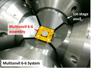
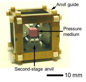
The multianvil 6-6 assembly is attached to the central cubic space formed with top surface
of the first-stage anvils of a cubic anvil multianvil apparatus (Nishiyama et al., 2008). This assembly is composed of a cubic cell assembly, six second-stage
anvils and an anvil guide.
The multianvil 6-6 system enables:
・High-precision anvil alignment
(well-controlled initial position of the second-stage anvils)
(well-controlled movement of the second-stage anvils)
・Simple and quick anvil replacement process
(different truncation size)
(different material (hardness, X-ray transparency))
(multianvil 6-6 and Kawai-type assemblies)
・Easiness of loading a small cell assembly (and gasket)
The second-stage anvils of the multianvil 6-6 assembly are characterized
by a truncated edge length, an edge length of a bottom surface and material.
In my experience, the truncated edge lengths are:
・1.5 and 2 mm (Kawazoe, 2014 in Japanese)
・2.5 and 3 mm (e.g. Kawazoe et al., 2010 HPR)
・4 mm (Kawazoe and Yamada, 2012)
・6 and 9 mm,
the edge lengths are:
・12 and 18 mm,
and materials are:
・Tungsten carbide
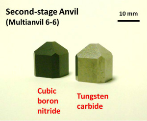
・Cubic boron nitride (Kawazoe et al. 2011)
・Sintered diamond
Some examples of the cell assemblies for the cubic anvil multianvil apparatus are shown below.
Fig.
(1st) The multianvil 6-6 assembly loaded in the deformation-DIA apparatus
(at Geodynamics research Center, Ehime University).
(2nd) The multianvil 6-6 assembly (Kawazoe et al., 2010 HPR).
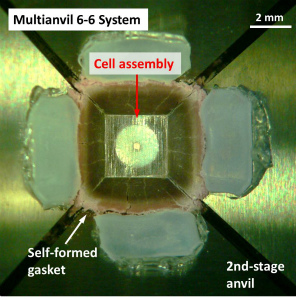
(3rd) A cell assembly after a deformation experiment on wadsleyite and
ringwoodite at 16 GPa and 1700 K (Kawazoe et al., 2010 PEPI).
(4th) The second-stage anvils for the multianvil 6-6 assembly. A cubic
boron nitride anvil is transparent for synchrotron X-ray (Kawazoe et al., 2011). |
| 4. Six Hydraulic Ram Multianvil Apparatus |
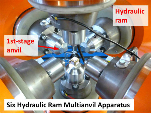 |
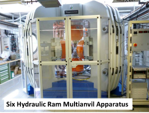
A six hydraulic ram multianvil apparatus allows us to perform:
・High-pressure static experiment (at high pressure)
・High-pressure deformation experiments (at high temperature)
This multianvil apparatus has six hydraulic rams. The sample pressure is generated by the successive compression.
(1) The six hydraulic rams drive six first-stage anvils.
(2) The first-stage anvils compress the second-stage anvils.
(3) The second-stage anvils compress the cell assembly.
The six hydraulic ram apparatus can be used as both the cubic anvil apparatus and the Kawai-type apparatus by setting inner modules of the Kawai-type or multianvil 6-6 system.
In addition, the six hydraulic rams are independently controlled in terms
of piston strokes or oil pressures. We can perform the high-pressure deformation experiments (at high temperature).
Fig. The six hydraulic ram multianvil apparatus (at Bayerisches Geoinstitut,
Manthilake et al., 2012). |
| 5. In Situ X-ray Measurements with Synchrotron Radiation |
 |
In situ X-ray measurements with synchrotron radiation allow us to perform:
・Diffraction
(phase identification, measuremnts of unit-cell volume and stress)
・Radiography
(measurements of length, strain and strain rate)
・Spectroscopy
at high pressure (and high temperature).
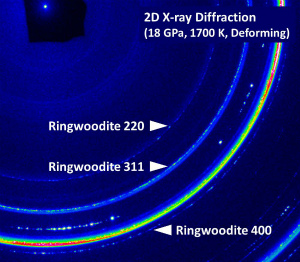
Two dimensional (radial) X-ray diffraction allows us to measure:
・Stress
・Grain size
・Crystallographic preferred oriencation (CPO) pattern
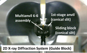
as a function of strain (deformation time). For diffracted X-rays, we need to place
・X-ray transparent materials (e.g. anvils) and
・Conical slits on the first-stage anvils and the sliding blocks
between a sample and a detector.
In high-pressure deformation experiments at the synchrotron facility, we can obtain rich information
about rheological properties of solid material as:
・Stress-strain curve
(tansient creep, steady-state creep, creep strength, flow law)
・Dynamic recrystallization (grain growth)
・CPO pattern transition
・Phase transformation during deformation
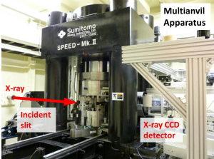
Fig.
(1sr) The multianvil apparatus "SPEED-Mk.II" (at BL04B1 beamline, SPring-8, Japan). The deformation-DIA guide
blocks were installed in 2010 (Kawazoe et al., 2011).
(2nd) 2D X-ray diffraction system of the lower guide blocks (the sliding
blocks) on downstream side. The conical slits are made on the first-stage
anvils and the sliding blocks for diffracted X-ray.
(3rd) A 2D X-ray diffraction pattern of ringwoodite deformed at 18 GPa
and 1700 K. |
| 6. Miniature Multianvil Apparatus for Optical Measurements |
 |
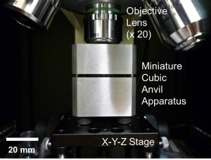
A miniature multianvil apparatus was developed (Kawazoe, 2012) for:
・Optical measurements at high pressure.
The miniature multianvil apparatus has unique features as follows:
・Optical access on a sample
・The smallest multianvil apparatus (as far as I know in 2015)
Compact (~53 mm in diamter and height)
Light (~530 g in weight)
・Press load is generated by tightening four screws
・Portable
・Less expensive
These feasures benefit easy application of the miniature multianvil apparatus
to various types of standard optical measurement systems.
The following optical measurements are possible at high pressure:
・Optical microscopy (visual observation)
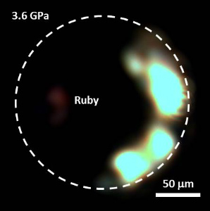
・Ruby fluorescence spectroscopy (in situ pressure measurement)
・Raman spectroscopy
・In situ X-ray diffraction
Fig. (1st) The miniature multianvil apparatus (Kawazoe, 2012) set under an objective lens of a confocal Raman spectrometer.
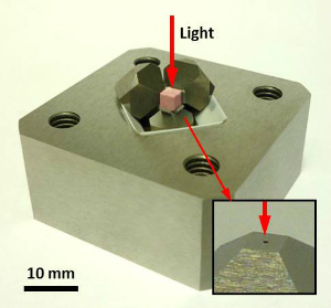
(2nd) A cubic cell assembly, anvils and a lower guide block of the miniature
multianvil apparatus. An inset shows a hole of the bottom anvil as optical
path.
(3rd) A photograph of a sample (a ruby chip) in NaCl pressure medium at
3.6 GPa in the miniature multianvil apparatus. |
| 7. Company |
|
|
Sumitomo Heavy Industries, Ltd. (Japan)
Max Voggenreiter GmbH (Germany)
The following multianvil apparatuses are at Bayerisches Geoinstitut.
・Kawai-type multianvil apparatus (DIA-type, Walker-type module)
・Six hydraulic ram multianvil apparatus
・Deformation-DIA apparatus
The following apparatus is at ID06 beamline in ESRF (European Synchrotron Radiation Facility).
・Deformation-DIA apparatus
The following apparatus will be installed at PETRA III in DESY (Deutsches Elektronen-Synchrotron).
・Six hydraulic ram multianvil apparatus |
II. Cell Assembly for a Multianvil Apparatus
| 1. Kawai-type Multianvil Apparatus (Synthesis Experiments) |
 |
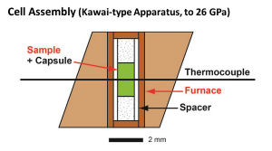
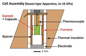
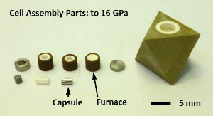
In the Kawai-type apparatus, the pressure medium is an octahedron. For high-pressure and high-temperature experiments, the cell assembly
is composed of the sample, the capsule, the furnace, (the thermal insulator, the electrodes, the thermocouple, etc).
Semi-sintered MgO is used as material of the pressure medium (Onodera et al., 1980). Cr or Co are doped for thermal insulation.
A furnace is made of
・Graphite (Kawai and Endo, 1970)
・LaCrO3 (Ohtani, 1979)
・Pt (Ito et al., 1972)
・Re
Thermocouples are:
・W97Re3-W75Re25 (Type D)
・W95Re5-W74Re26 (Type C).
Cu protection coils likely affect on temperature reading (Nishihara et al., 2006).
Capsule materials are:
・Graphite
・Ni
・Mo (relatively low oxygen fugacity)
・Re (relatively high oxygen fugacity)
・Pt (to keep water, welding or cold sealing)
・NaCl, etc.
Some examples are shown below.
Fig. 1st and 2nd
Schematic illustrations of cross sections of the cell assemblies for the
Kawai-type multianvil apparatus. (1st) 7/3 cell assembly. Parts of 7/3
cell assembly are shown below. (2nd) 14/8 cell assembly. Parts of 14/8
cell assembly and a recovered cell assembly are shown below.
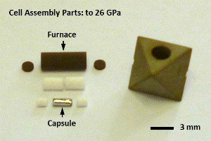
Fig. 3rd
7/3 cell assembly to 26 GPa and ~2000 C for the synthesis of alminous bridgmanite in the Kawai-type multianvil apparatus.
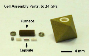
Fig. 4th
10/4 cell assembly to 24 GPa and ~2000 C for the synthesis of ringwoodite and majorite in the Kawai-type multianvil apparatus. We employ a straight LaCrO3 furnace and ZrO2 thermal insulator.
Fig. 5th and 6th.
14/8 cell assembly to 16 GPa and ~1800 C for the synthesis of wadsleyite and hydrous wadsleyite in the Kawai-type multianvil apparatus. (5th) Parts of 14/8 cell assembly. We employ a LaCrO3 stepped furnace and ZrO2 thermal insulator. A schematic cross section of the cell assembly is shown
in Fig. 2nd. (6th) The cell assembly recovered from 15 GPa after synthesis
of hydrous wadsleyite. In this case, the capsule material was Pt. |
|
For room-temperature pressure calibration experiments, the cell assembly is simply composed of a pressure medium, sample (pressure calibrant) and two or four electrodes. |
| 2. Cubic Anvil Apparatus (Deformation-DIA Apparatus) |
 |
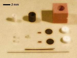
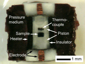
In the cubic anvil apparatus, a pressure medium is a cube. For high-pressure and high-temperature experiments, the cell assembly
is composed of a sample, a capsule, a furnace, (a thermal insulator, electrodes, a thermocouple, etc).
Our group uses semi-sintered MgO as material of the pressure medium (Onodera et al., 1980). Co is doped to the MgO to generate high temperature. In addition, pressure generation efficiency with the Co-doped MgO was better than the semi-sintered MgO (Kawazoe et al., 2010 HPR).
Our group have developed the cell assemblies to allows us to perform:
・High-pressure experiments to 20 GPa at 2000 K
(Kawazoe et al., 2010 PEPI)
・Deformation experiments to 20 GPa at 1700 K
(Kawazoe et al., 2010 JES)
・In situ stress-strain measurements to 15 GPa and 1700 K
(Kawazoe et al., 2011)
Fig.
(1st) Cell assembly parts for high-pressure experiments with a cubic anvil
apparatus: pressure medium: (Mg,Co)O, heater: LaCrO3, insulator: MgO, deformation piston: Al2O3, sample: olivine, outer electrode: Cu wire, inner electrode: Mo disk,
thermocouple: W-Re wire.
(2nd) A cell assembly used for a deformation experiment on ringwoodite
at 20 GPa and 1700 K (Kawazoe et al., 2010 JES).
(3rd) A cell assembly used for a deformation experiment on wadsleyite in
simple shear geometry at 18 GPa and 1800 K (Kawazoe et al., 2013). |
| 3. Calibration Materials for Room-Temperature Pressure Calibration |
|
Examples of calibration materials for room-temperature pressure calibration
are:
・Bi
・ZnTe (Kusaba et al.)
・ZnS
・GaAs
・GaP |
| 4. Machining of Cell Assembly Parts for a Multianvil Apparatus |



 |
These cell assembly parts of the multianvil experiments are unfortunately
broken after one experiment. Therefore, a new set of the cell assembly parts is necessary to be made for every experiment.
Fig. A modeling machine (at Department of Earth & Planetary Systems
Science at Hiroshima University)..
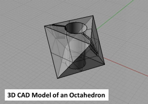
Fig. A 3D CAD model of an octahedron of the 14/8 cell assembly.
A precise drilling machine is used to precisely drill holes in the cell assembly parts.
We put a furnace, thermocouple wires, etc. in the holes in the pressure medium.
Fig. A precise drilling machine (at Department of Earth & Planetary
Systems Science at Hiroshima University).
Fig. A laser cutter (at Department of Earth & Planetary Systems Science
at Hiroshima University).
A precise welder is used to precisely weld a metallic capsule.
Fig. A precise welder (at Department of Earth & Planetary Systems Science
at Hiroshima University).
Fig. A precise cutter (at Department of Earth & Planetary Systems Science
at Hiroshima University). |
 |
A stereomicroscope is used to make and assemble the ceramic cell assembly parts.
Fig. A stereomicroscope (at Department of Earth & Planetary Systems
Science at Hiroshima University). |
 |
A small furnace is used to remove moisture in ceramic cell assembly parts.
This furnace can reach 1000 C.
Fig. A small furnace (at Department of Earth & Planetary Systems Science
at Hiroshima University).
|
| 5. Dummy Metal Block |
|
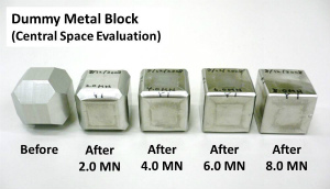 |
A dummy metal block is compressed to evaluate deformation of the central
cubic space formed with top surface of the first-stage anvils in a cubic
anvil apparatus and a Kawai-type apparatus.
The minimum deviation of the central cubic space from the true cube is
a key for extension of pressure range in a cubic anvil apparatus and a
Kawai-type apparatus. |
III. Rotational Drickamer Apparatus
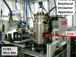 |
A rotational Drickamer apparatus (RDA) allows us to perform
・High-pressure deformation experiments (at high temperature)
・In situ stress-strain measurements
(e.g. Kawazoe et al., 2009; Kawazoe et al., 2010 JGR).
Fig. The rotational Drickamer apparatus (RDA) at X17B2 beamline, National
Synchrotron Light Source (NSLS), Brookhaven National Laboratory (BNL),
USA. |
IV. Sample Analyses
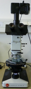 |
【Polarization Microscope】
A usefull text "Guide to Thin Section Microscopy (Raith, Raase & Reinhardt)" can be found at a web site of the
Deutsche Mineralogische Gesellschaft.
Fig. Polarization microscope (Bayerisches Geoinstitut, University of Bayreuth). |
| Calculation: Press Load |
A relationship between a total press load and a press load of each anvil
in DIA-type and six-ram-type copression.
A press load of each first-stage anvil is one third of a total press
load applied to a cubic assembly.
In other words, the total press load applied to the cubic assembly is
the press load of each first-stage anvil multiplied by 3.
|
A relationship of a press load between Kawai-type systems with [111]-direction
and [100]-direction compression.
A Kawai-type compression system with the [111]-direction compression
is efficinet compared with that with the [100]-direction compression by
a factor of a sqare root 3. In other words, you need more press load by
a factor of a square root 3 with the [100]-direction compression compared
with that with the [111]-direction compression. |
Conversion of a force unit used for a multi-anvil experiment: 100 tonf
= 1 MN
F = mg, where F is force, m is mass, and g is gravitational accelerationt
(here I adopt g = 9.8 or 10 for simplicity).
1 N = 1 kg * 9.8 m/s^2 = 9.8 kgf ~ 10 kgf
1000 kgf = 10^3 kgf = 1 tonf
1 MN = 10^6 N = 10^5 kgf = 10^(5-3) tonf = 100 tonf |
|


